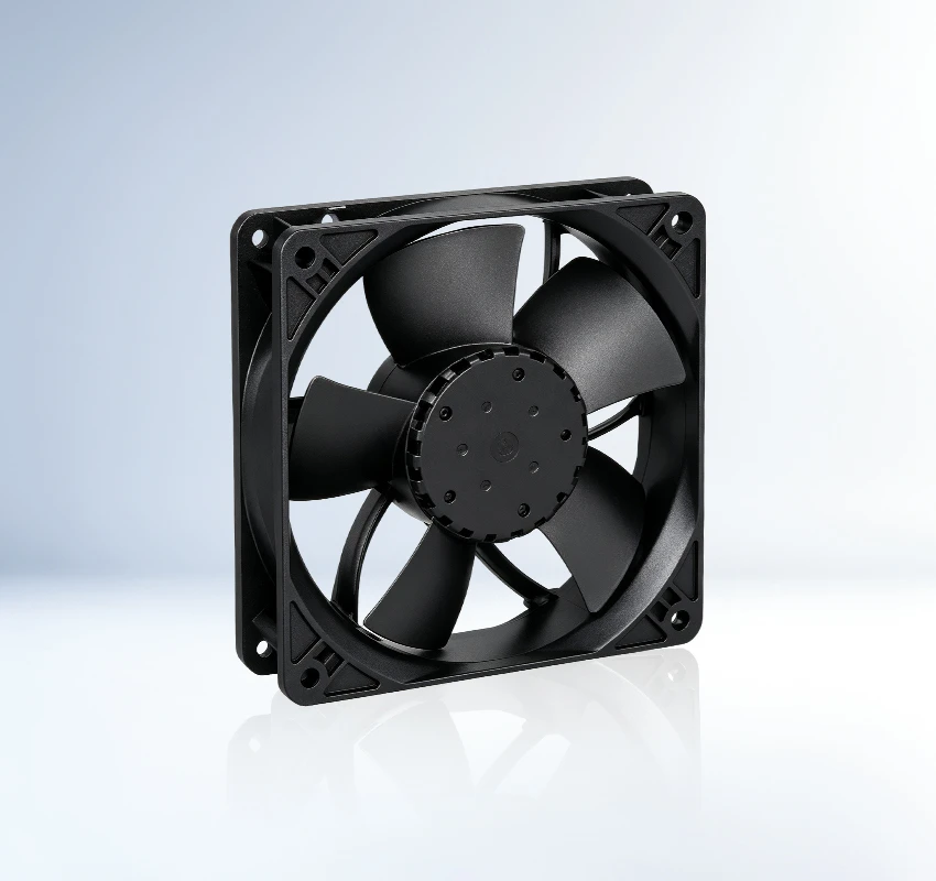
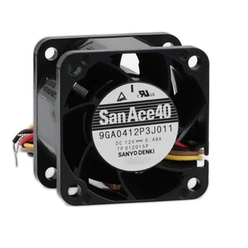
The 9GA0412P3J011 is a Sanyo Denki 12 VDC, 40 × 40 × 28 mm DC axial fan for servers, UPS systems, and telecom equipment. Long-life series construction is the main characteristic stated in the supplied reference. For controller selection, start with the supplied cooling output. Use current model documentation to validate protection choices.
| Rated Voltage(V) | 12 |
|---|---|
| Size(mm) | 40*40*28 |
| Max.Air Flow(m³/h) | 40.29 |
| Max.Pressure(Pa) | 535 |
| Input Power(W) | 5.88 |
| Speed(rpm) | 18000 |
| Noise(db) | 54 |
The SANYO DENKI 9GA0412P3J011 is a DC axial fan developed for servers, storage systems and ICT equipment. Its directed airflow helps remove heat from densely arranged components and supports predictable equipment temperatures.
With up to 40.29 m3/h airflow and 535 Pa static pressure, the model can move cooling air through vents, filters and compact internal passages. Buyers should confirm the complete suffix, connector, sensor output and control option before ordering. Engineers should validate the operating point with the actual grille and filter.
Review grille loss at the required duty point. It supports a clear fan specification for future servicing. Confirm the final fan curve in the assembled equipment.
The San Ace 9GA0412P3J011 supports thermal management in server chassis and computing nodes. Reliable ventilation reduces hot spots around sensitive electronics and supports consistent equipment availability. It provides a practical cooling path for OEM integration.
For storage arrays and data appliances, 9GA0412P3J011 provides a dedicated forced-air cooling path. Reliable ventilation reduces hot spots around sensitive electronics and supports consistent equipment availability. It provides a practical cooling path for OEM integration.
SANYO DENKI 9GA0412P3J011 serves network and other ICT hardware that operate with sustained internal heat. Reliable ventilation reduces hot spots around sensitive electronics and supports consistent equipment availability. It provides a practical cooling path for OEM integration.
Check its 40 × 40 × 28 mm size, 40.29 m³/h airflow, 535 Pa pressure, mounting points, airflow direction, and system resistance.
It is listed for servers, UPS systems, and telecom equipment. Confirm airflow, pressure, dimensions, and environmental conditions against the actual equipment.
Match voltage, size, mounting, airflow direction, airflow, pressure, connector, control signal, and protection before substitution.
Inspect dust buildup, airflow blockage, abnormal noise, mounting security, and wiring condition; disconnect power before service.
Compare its listed power with the required airflow, pressure, and operating hours. System-level savings depend on correct duty-point selection.
The worksheet lists 12 VDC. Check polarity or AC frequency and the wiring diagram before commissioning.