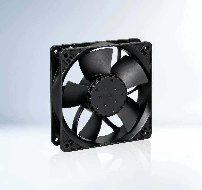
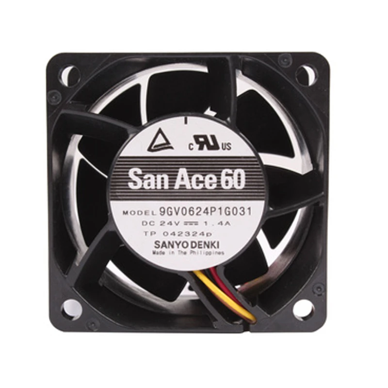
The 9GV0624P1G031 is a Sanyo Denki 24 VDC, 60 × 60 × 38 mm DC axial fan for industrial controls, power cabinets, and energy systems. High airflow is highlighted together with a high-static-pressure design. For thermal validation, start with the supplied volume-flow figure. Verify the exact bearing and signal options in the datasheet.
| Rated Voltage(V) | 24 |
|---|---|
| Size(mm) | 60*60*38 |
| Max.Air Flow(m³/h) | 142.8 |
| Max.Pressure(Pa) | 752.3 |
| Input Power(W) | 33.6 |
| Speed(rpm) | 16000 |
| Noise(db) | 66 |
SANYO DENKI positions 9GV0624P1G031 as a DC axial fan for automation controls, PLC cabinets and drive systems. It helps equipment designers manage local hot spots where natural convection is insufficient.
The rated peak airflow of 142.8 m3/h combines with 752.3 Pa pressure capability to support useful flow after installation losses are considered. For design approval, verify airflow direction, connector details and available control signals. Prototype testing should include the final vents, guards and component loading.
Qualify performance with the production guard. The outcome supports dependable long-term equipment service. Confirm the final fan curve in the assembled equipment. Preserve clear inlet and outlet space during installation.
For automation and electrical control cabinets, 9GV0624P1G031 provides a dedicated forced-air cooling path. Air circulation around processors, power devices and control electronics limits heat concentration and supports stable operation. The application supports stable equipment service.
SANYO DENKI 9GV0624P1G031 serves PLC and motion-control equipment that operate with sustained internal heat. Air circulation around processors, power devices and control electronics limits heat concentration and supports stable operation. The application supports stable equipment service.
9GV0624P1G031 is suitable for inverters and industrial drive systems. These systems need continuous heat removal because compact layouts and rising power density restrict natural convection. The application supports stable equipment service. Selection should follow the approved full model code.
The worksheet lists 66 dB. Enclosure acoustics, system resistance, and distance can change the installed result.
Verify supply, connector, obstructions, impeller movement, and alarm or protection status using the model-specific troubleshooting data.
Confirm connector and mounting details, keep the airflow path clear, and isolate power before cleaning or service.
Check its 60 × 60 × 38 mm size, 142.8 m³/h airflow, 752.3 Pa pressure, mounting points, airflow direction, and system resistance.
It is listed for industrial controls, power cabinets, and energy systems. Confirm airflow, pressure, dimensions, and environmental conditions against the actual equipment.