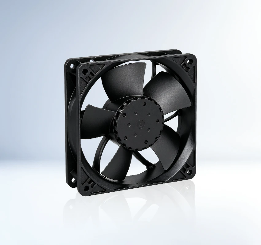
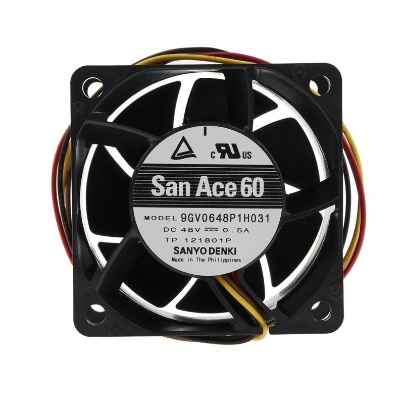
The 9GV0648P1H031 is a Sanyo Denki 48 VDC, 60 × 60 × 38 mm DC axial fan for industrial controls, power cabinets, and energy systems. Series focus: high airflow and pressure. For replacement evaluation, start with the supplied rated dataset. Check the full suffix before confirming connector details. Focus: duty point matching speed benchmark.
| Rated Voltage(V) | 48 |
|---|---|
| Size(mm) | 60*60*38 |
| Max.Air Flow(m³/h) | 127.8 |
| Max.Pressure(Pa) | 617.7 |
| Input Power(W) | 24 |
| Speed(rpm) | 14500 |
| Noise(db) | 63 |
The SANYO DENKI 9GV0648P1H031 is a DC axial fan developed for automation controls, PLC cabinets and drive systems. Its directed airflow helps remove heat from densely arranged components and supports predictable equipment temperatures.
Its 127.8 m3/h maximum airflow supports rapid air exchange, while 617.7 Pa pressure capability helps overcome resistance within the finished equipment. Procurement teams should match the entire part number to the approved specification. Thermal testing in a representative chassis confirms cooling margin before volume release.
Qualify performance with the production guard. The outcome supports dependable long-term equipment service. Confirm the final fan curve in the assembled equipment.
SANYO DENKI 9GV0648P1H031 serves automation and electrical control cabinets that operate with sustained internal heat. These systems need continuous heat removal because compact layouts and rising power density restrict natural convection. This helps maintain dependable equipment operation.
9GV0648P1H031 is suitable for PLC and motion-control equipment. Directed airflow carries component heat toward the equipment exhaust and helps maintain a controlled internal temperature. This helps maintain dependable equipment operation. Selection should follow the approved full model code.
The San Ace 9GV0648P1H031 supports thermal management in inverters and industrial drive systems. Directed airflow carries component heat toward the equipment exhaust and helps maintain a controlled internal temperature. This helps maintain dependable equipment operation.
Verify supply, connector, obstructions, impeller movement, and alarm or protection status using the model-specific troubleshooting data.
Confirm connector and mounting details, keep the airflow path clear, and isolate power before cleaning or service.
Check its 60 × 60 × 38 mm size, 127.8 m³/h airflow, 617.7 Pa pressure, mounting points, airflow direction, and system resistance.
It is listed for industrial controls, power cabinets, and energy systems. Confirm airflow, pressure, dimensions, and environmental conditions against the actual equipment.
Review ambient temperature, airflow restriction, contamination exposure, noise limit, mounting orientation, and maintenance access.
The worksheet lists 127.8 m³/h. Compare the operating point with system resistance and the official performance curve.