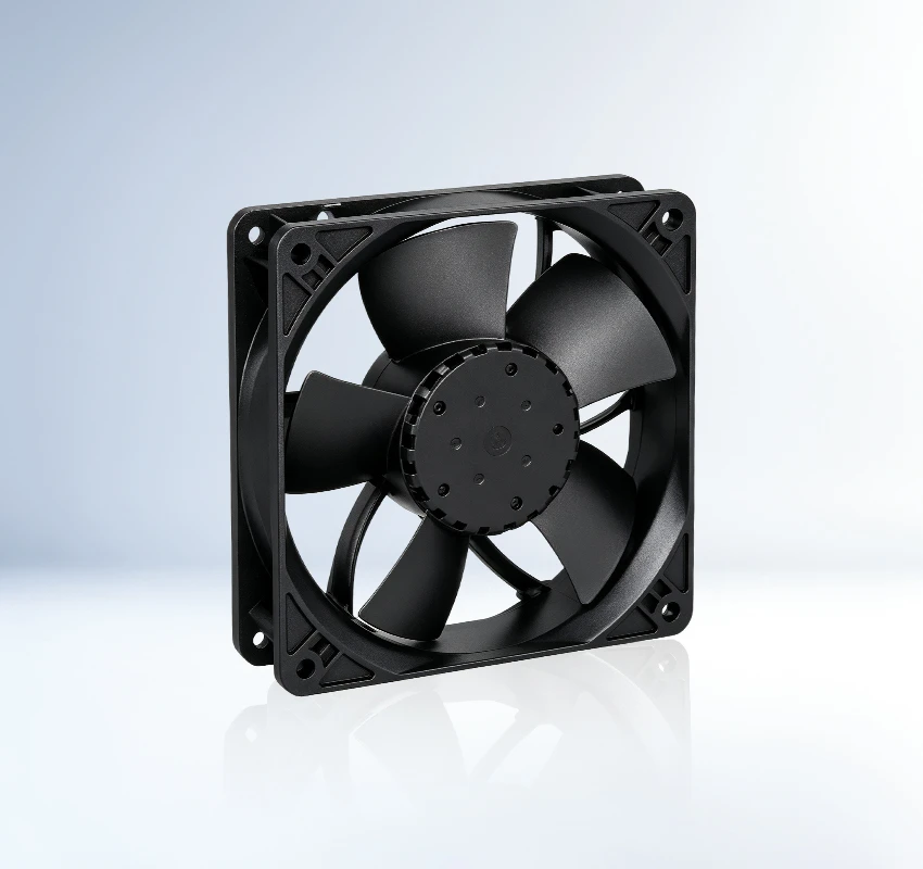
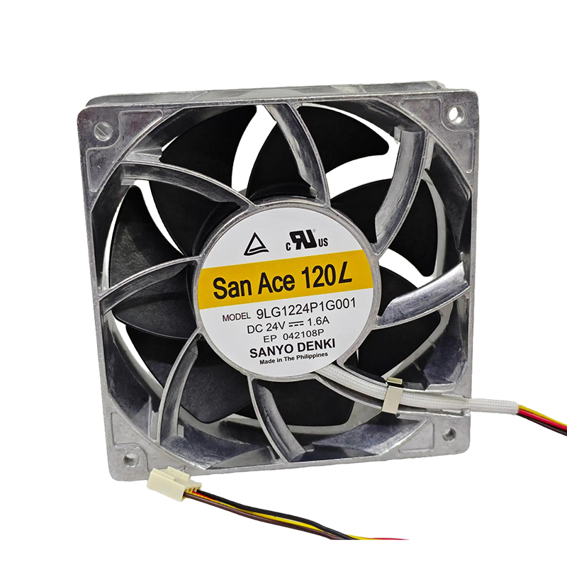
Within telecom and network equipment, Sanyo Denki 9LG1224P1G001 operates as a 119 × 119 × 38 mm DC axial fan at 24 VDC. No exact entry appears in the supplied feature table, so bearing, control, and protection details require datasheet confirmation. 38.4 W input is the defining electrical-load figure. Focus: service access planning motor input.
| Rated Voltage(V) | 24 |
|---|---|
| Size(mm) | 119*119*38 |
| Max.Air Flow(m³/h) | 419.9 |
| Max.Pressure(Pa) | 368.7 |
| Input Power(W) | 38.4 |
| Speed(rpm) | 6550 |
| Noise(db) | 62 |
9LG1224P1G001 is intended for dependable forced-air cooling in telecom cabinets and network equipment. This SANYO DENKI DC axial fan fits equipment designs where thermal stability affects service continuity.
The rated peak airflow of 419.9 m3/h combines with 368.7 Pa pressure capability to support useful flow after installation losses are considered. For design approval, verify airflow direction, connector details and available control signals. Prototype testing should include the final vents, guards and component loading.
Qualify performance with the production guard. It also creates a clearer thermal approval record. Confirm the final fan curve in the assembled equipment. Preserve clear inlet and outlet space during installation.
For telecom cabinets and radio-access equipment, 9LG1224P1G001 provides a dedicated forced-air cooling path. Air circulation around processors, power devices and control electronics limits heat concentration and supports stable operation. The application supports stable equipment service.
SANYO DENKI 9LG1224P1G001 serves routers, switches and edge-network hardware that operate with sustained internal heat. Air circulation around processors, power devices and control electronics limits heat concentration and supports stable operation. The application supports stable equipment service.
The exact bearing is not stated in the supplied row. Confirm it from the complete model suffix and current Sanyo Denki datasheet.
Check its 119 × 119 × 38 mm size, 419.9 m³/h airflow, 368.7 Pa pressure, mounting points, airflow direction, and system resistance.
It is listed for telecom and network equipment. Confirm airflow, pressure, dimensions, and environmental conditions against the actual equipment.
Match voltage, size, mounting, airflow direction, airflow, pressure, connector, control signal, and protection before substitution.
The worksheet lists 419.9 m³/h. Compare the operating point with system resistance and the official performance curve.