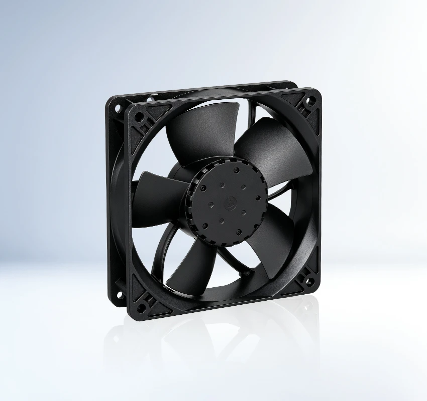
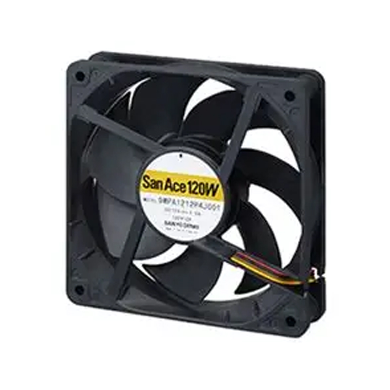
Built around outdoor equipment and photovoltaic inverters, Sanyo Denki 9WPA1224J4001 is a 24 VDC DC axial fan in a 120 × 120 × 25 mm frame. Its listed airflow of 255 m³/h is the standout performance value. Control and monitoring availability is suffix-specific according to the supplied reference. Focus: duty point matching supply requirement.
| Rated Voltage(V) | 24 |
|---|---|
| Size(mm) | 120*120*25 |
| Max.Air Flow(m³/h) | 255 |
| Max.Pressure(Pa) | 210 |
| Input Power(W) | 12 |
| Speed(rpm) | 5400 |
| Noise(db) | 53 |
For energy storage, photovoltaic inverters and charging equipment, the SANYO DENKI 9WPA1224J4001 provides DC axial fan cooling in an integration-ready format. It establishes an active air path through restricted equipment spaces.
A listed maximum airflow of 255 m3/h and maximum pressure of 210 Pa give engineers a clear basis for matching the fan to enclosure resistance. Buyers should confirm the complete suffix, connector, sensor output and control option before ordering. Engineers should validate the operating point with the actual grille and filter.
Assess vibration transfer into enclosure panels. It helps maintenance teams plan compatible replacements. Confirm the final fan curve in the assembled equipment.
9WPA1224J4001 is suitable for energy storage systems and PCS equipment. These systems need continuous heat removal because compact layouts and rising power density restrict natural convection. It provides a practical cooling path for OEM integration.
The San Ace 9WPA1224J4001 supports thermal management in photovoltaic inverter equipment. These systems need continuous heat removal because compact layouts and rising power density restrict natural convection. It provides a practical cooling path for OEM integration.
For electric-vehicle charging equipment, 9WPA1224J4001 provides a dedicated forced-air cooling path. These systems need continuous heat removal because compact layouts and rising power density restrict natural convection. It provides a practical cooling path for OEM integration.
Verify supply, connector, obstructions, impeller movement, and alarm or protection status using the model-specific troubleshooting data.
Confirm connector and mounting details, keep the airflow path clear, and isolate power before cleaning or service.
Check its 120 × 120 × 25 mm size, 255 m³/h airflow, 210 Pa pressure, mounting points, airflow direction, and system resistance.
Evaluate the exact bearing, life, temperature, alarm, and protection data. Correct sizing and clean airflow are also required for reliable operation.
Review ambient temperature, airflow restriction, contamination exposure, noise limit, mounting orientation, and maintenance access.